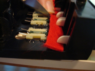
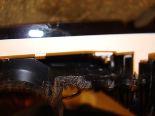
 | The author installs the cloth shim on to the keyboard tray. |
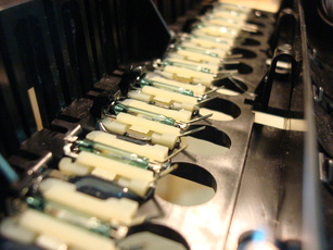
 | A set of keys with their first set of magnets hot glued on |
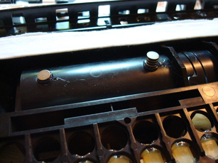
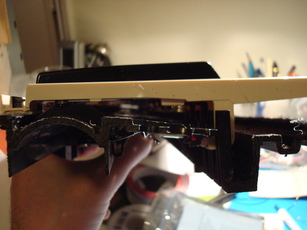
 | The keyboard tray |
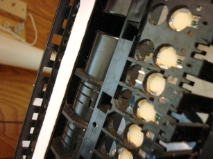 | The keyboard tray |
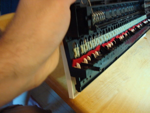
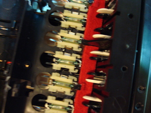
 | Reed switches glued to the bottom of the keyboard tray |
 | The first octave or so of reed switches on the bottom of the keyboard tray |
 | A set of white keys with both set of magnets hot glued on |
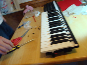
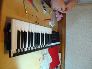
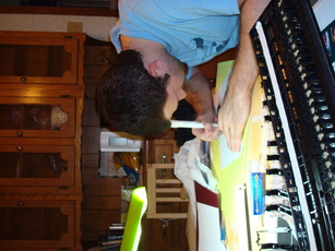 | The author's roommate cutting stencils |
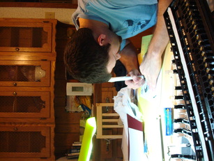 | The author's roommate cutting stencils |
 | Repelling magnets glued to the keyboard tray, one of which has a stack of magnets on top of it to increase its repelling force |
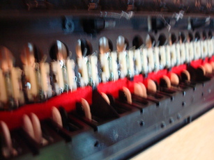
 | The keyboard assembled with three octaves |
 | The keyboard assembled with three octaves in a dynamic action shot |
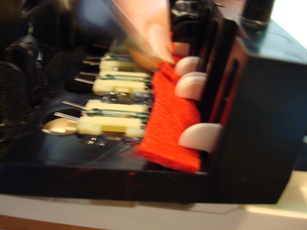
 | The author prepares to install adhesive felt. |
 | The adhesive felt |
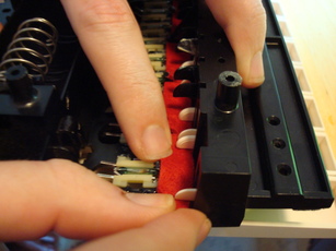
 | The adhesive felt as first installed, before making cuts to accomidate plastic posts |
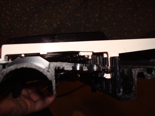
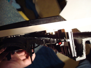
 | The underside of the keyboard tray |
 | Detail showing the cuts made in the adhesive felt |
 | Underside of the keyboard tray |
 | Underside of the keyboard tray |
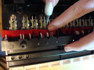
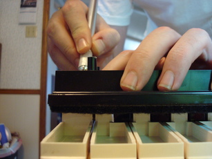
 | The author making cuts in the adhesive felt |
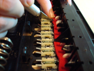 | The author making cuts in the adhesive felt |
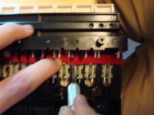
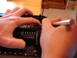
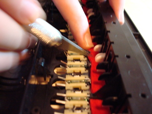 | The author making cuts in the adhesive felt |
 | The author making cuts in the adhesive felt |
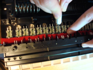
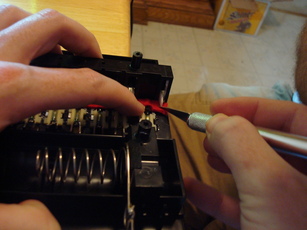
 | The author making cuts in the adhesive felt |
 | The author making cuts in the adhesive felt |
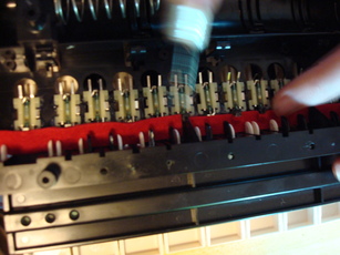
 | The author making cuts in the adhesive felt |
 | The author making cuts in the adhesive felt |
 | The author making cuts in the adhesive felt |
 | The author making cuts in the adhesive felt |
 | The author making cuts in the adhesive felt |
 | The author making cuts in the adhesive felt |
 | The author making cuts in the adhesive felt |
 | The keyboard connected to the circuit board, in turn connected to a simple voltage controlled oscillator |
 | The circuit board |
 | Detail of the connector between the circuit board and the keyboard |
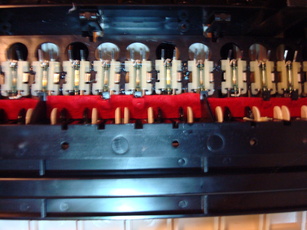
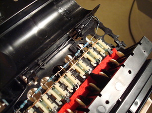
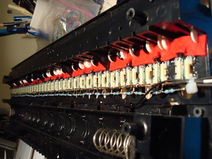 | The underside of the completed keyboard with resistor chain and common buss |
 | Detail of how the resistor chain was soldered directly to the terminals of the reed switches |
 | The underside of the keyboard showing upswing stops of keys, resistor chain, and reed switches |
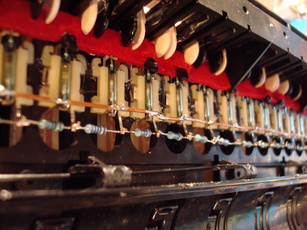
 | View through the center of the keyboard |
 | View through the center of the keyboard |
 | View through the center of the keyboard |
 | View through the center of the keyboard |
 | The end of the resistor chain and ground wire routed through underside of keyboard |
 | The completed keyboard with completed circuit board |


